The metrology area of a wafer fab recently hit a headache: its newly introduced e-beam review equipment frequently produced image drift, and defect classification accuracy fell short of acceptance targets; the two bright-field defect inspection tools next to it also had false-alarm rates noticeably higher than the manufacturer's rated values. The equipment engineers checked the software parameters and ran the recipes countless times, but the problem persisted. Only when the facilities department brought in an external vibration expert did testing reveal the cause: the metrology area was adjacent to the MAU air-handling units, whose operational vibration traveled through the raised floor to the tools; worse, the vacuum pump room was directly below, and 20–50 Hz pump vibration "climbed" up through the floor slab, landing right in the band most sensitive for optical inspection systems. Semiconductor metrology equipment does the job of "finding faults at the nanometer scale"—CD-SEM measures critical dimensions of a dozen or so nanometers, defect inspection must catch defects of a few tens of nanometers, and bright-/dark-field systems respond to even sub-micron vibration. The level of vibration control in the metrology area directly determines the tools' false-alarm rate, miss rate, and re-measurement consistency. This article explains the logic of configuring vibration isolation for semiconductor metrology equipment, helping wafer fabs, OSAT fabs, and university microelectronics cleanrooms avoid common pitfalls.
Configuring vibration isolation for semiconductor metrology equipment is completely different from that for process tools such as lithography and etching: process tools can rely on their own foundations or internal isolation, whereas metrology equipment is "accuracy-sensitive"—external environmental vibration enters the measurement results directly. Industry practice is to control metrology-area vibration to VC-D grade or above, and VC-E grade is recommended for e-beam metrology equipment. There are three configuration principles: e-beam equipment (CD-SEM, e-beam review) should prioritize active isolation; optical inspection equipment (bright-/dark-field defect inspection, film thickness metrology) should mainly use pneumatic isolation, upgrading to active isolation when low-frequency limits are exceeded; and all metrology tools must maintain a reasonable distance from, or be isolated from, strong vibration sources such as vacuum pumps and MAU units. LeadTop has focused on precision vibration isolation for over a decade and has provided metrology equipment isolation fit-outs for multiple wafer fabs, OSAT companies, and university micro/nano fabrication platforms, matching optimal solutions by tool type and facility conditions. LeadTop's product line covers all semiconductor metrology scenarios: LVH series (heavy-duty active isolation, for CD-SEM/e-beam equipment), VCM series (active isolation strips, for retrofit and space-constrained scenarios), ZDT series (pneumatic isolation platforms, for optical inspection tools), TA series (tabletop active isolation tables, for small metrology equipment), and POT series (solid-state isolators, for auxiliary equipment).
|
Tool type |
Measurement principle |
Typical vibration target |
Main sensitive band |
Recommended isolation solution |
|
CD-SEM/e-beam review |
Electron-optical imaging |
VC-E grade and above |
Full band, especially low frequency |
LVH series active isolation |
|
Bright-field/dark-field defect inspection |
Optical imaging scanning |
VC-D grade |
10–100 Hz |
ZDT-B pneumatic or LVH active isolation |
|
OCD/film thickness metrology |
Spectroscopic ellipsometry |
VC-D grade |
10–200 Hz |
ZDT-B/ZDT-P pneumatic isolation |
|
Overlay metrology |
Optical imaging comparison |
VC-D grade and above |
Mainly low frequency |
LVH series or ZDT-B pneumatic |
|
Wafer geometry/warpage metrology |
Optical interferometry |
VC-C grade and above |
Mid-to-high frequency |
ZDT-P pneumatic or TA series active |
Recommended practice: when planning the metrology area, first finalize the tool list, compare each tool against the manufacturer's vibration environment requirements (most manufacturers specify vibration tolerances in their technical specifications), and then formulate a unified zoning and isolation plan. LeadTop provides vibration environment assessment for metrology areas and issues tool-by-tool compliance plans.
Semiconductor plants and cleanrooms have far more vibration sources than ordinary laboratories: FFU fan filter units (high-frequency broadband), MAU make-up air units (low-frequency broadband), vacuum pumps (20–50 Hz), cooling water systems (pump and piping vibration), and elevators and material handling equipment (transient impacts). Metrology area planning should follow the "avoid first, isolate second" principle: keep the metrology area as far as possible from strong vibration sources such as MAU units, vacuum pump rooms, and cooling towers, with at least one fire compartment separation or staggered floor layout; e-beam equipment should preferably be placed on solid floor-slab areas rather than large-span raised-floor areas to reduce structural amplification effects; for vibration sources that cannot be avoided, source-side isolation should be done first (vibration pads under pump sets, flexible couplings in piping), followed by receiver-side isolation at the tool.
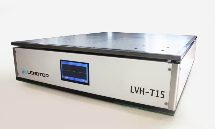
Electron-optical equipment such as CD-SEM and e-beam defect review: LeadTop's LVH series heavy-duty active isolation platform is recommended, with load capacity of 0.5–5 t, response time ≤8 ms, and excellent isolation performance across the 0.5–20 Hz band, canceling facility low-frequency vibration in real time and keeping tool vibration at VC-E grade. Tools with greater self-weight can choose the LVH-T15 heavy-duty active isolation (load capacity from the 500 kg class to several tonnes), where electromagnetic actuators combined with four-stage air springs deliver both low-frequency active control and high-frequency passive isolation.
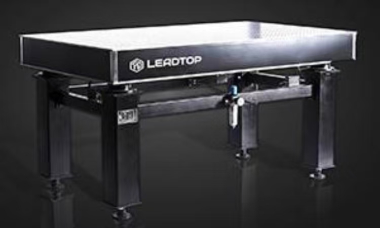
Optical equipment such as bright-field/dark-field defect inspection, OCD, and film thickness metrology: the mainstream choice is LeadTop's ZDT-B pneumatic isolation platform (natural frequency 1.0–1.5 Hz, 99% isolation efficiency above 10 Hz), with pneumatic auto-leveling of ±10 mm and suitability for raised-floor installation. If on-site low-frequency vibration (<10 Hz) exceeds limits, upgrade to LVH series active isolation or VCM series active isolation strips.
For acceptance of semiconductor metrology tool isolation, a four-level confirmation is recommended: no-load vibration testing (tabletop vibration meets the target with the tool unpowered); loaded vibration testing (vibration does not degrade after the tool is powered on and running); tool acceptance standard-wafer testing (run the acceptance recipe with a standard wafer, with defect detection rate and CD measurement accuracy reaching acceptance targets); and long-term stability tracking (continuous operation for more than a week, observing false-alarm rate and image drift trends). During operation, periodic vibration re-measurement at key points in the metrology area is recommended to track changes in vibration sources such as newly added equipment and retrofit construction. LeadTop provides full-process acceptance services and issues vibration test reports.
Vibration Isolation Retrofit of the Metrology Area at a Semiconductor Inspection Company in Wuxi
The company provides third-party inspection services for wafer foundries. Its metrology area is equipped with one CD-SEM and two bright-field defect inspection tools. The metrology area is located on the raised-floor section of the second floor of the cleanroom, adjacent to the MAU units, with a vacuum pump room below. After commissioning, the CD-SEM frequently suffered image drift and defect review classification accuracy fell short of targets; the bright-field tools' false-alarm rate ran about 4 percentage points above the rated value, and rework and re-measurement consumed a large amount of capacity.
Testing by the LeadTop technical team found that metrology-area tabletop vibration exceeded limits in two bands—5–15 Hz (dominated by the MAU units) and 20–50 Hz (dominated by the vacuum pumps)—and that vibration at the CD-SEM installation position exceeded VC-E grade requirements by about 2 times. Retrofit plan: the CD-SEM was equipped with a LeadTop LVH series heavy-duty active isolation platform; the two bright-field defect inspection tools were equipped with ZDT-B pneumatic isolation platforms; in addition, vibration pads were added under the pump sets in the vacuum pump room and the piping was refitted with flexible couplings to reduce vibration output at the source.
Post-retrofit measurements: CD-SEM tool vibration dropped within VC-E grade, with attenuation >35 dB at 5 Hz; the bright-field tools met VC-D grade. In re-measurement acceptance, the CD-SEM images were stable with no drift, and defect review classification accuracy reached the acceptance targets; the bright-field tools' false-alarm rate returned to within the rated range. According to the company's equipment lead: "The re-measurement rate dropped a lot after the retrofit, customer complaints decreased, and the capacity bottleneck was resolved."
|
Comparison dimension |
||||
|
Compatible tools |
Auxiliary equipment, front-end finishing tables |
Optical inspection/film thickness metrology |
Retrofit scenarios, space-constrained tools |
CD-SEM, e-beam review, overlay metrology |
|
Natural frequency |
4–12 Hz |
1.0–1.5 Hz |
≤1.5 Hz |
≤1.5 Hz |
|
Low-frequency isolation (<10 Hz) |
Limited |
Fair |
Excellent (active control) |
Excellent (response ≤8 ms) |
|
Air supply required |
No |
Yes |
No (power only) |
No (power only) |
|
Installation features |
Ready to use |
Requires air supply lines, suited to raised floors |
Modular, no tool relocation needed |
Whole-platform or modular installation |
|
Recommended use |
Auxiliary equipment |
Standard for optical metrology tools |
First choice for existing production line retrofits |
Standard for e-beam metrology equipment |
LeadTop summary: e-beam metrology equipment (CD-SEM/review/overlay) should use LVH series active isolation; optical inspection and metrology tools should use ZDT series pneumatic isolation; existing production line retrofits and space-constrained scenarios should use VCM series active isolation strips; for strong vibration sources (vacuum pumps/MAU), perform source-side damping first, then tool-side isolation.


Q1: Many semiconductor tools come with built-in air springs—do we still need external isolation?
A: The built-in air springs of a tool mainly isolate high-frequency vibration generated by the tool's internal moving parts (such as scanning stages and robotic arms), and have limited capability against low-frequency vibration (<10 Hz) transmitted from the building foundation. Because metrology equipment is sensitive to low-frequency vibration, whether external isolation is needed depends on the measured results at tool acceptance: if vibration meets the standard and acceptance passes, it can be omitted; if not, external isolation is required. It is recommended to rely on the tool acceptance standard-wafer test results, and not to assume that "built-in air springs mean no isolation needed."
Q2: Is there a difference in isolation solutions between tools on raised floors and tools on solid floor slabs?
A: Yes. Raised floors (perforated panels with a high open-area ratio supported on pedestals) amplify vibration, so the vibration environment for tools is usually worse than on solid floor slabs; in addition, the space beneath a raised floor is limited and air supply lines are difficult to route. For metrology tools on raised floors, active isolation is recommended as the priority (LVH/VCM series, no air supply needed); pneumatic isolation (ZDT series) can be chosen on solid floor-slab areas. When planning a new plant, it is recommended to reserve a solid floor-slab area for the metrology zone.
Q3: How far should the metrology area be from lithography tools? Are there spacing requirements?
A: There is no single fixed spacing; it depends on whether isolation measures exist in between and on the floor structure. Common practice is to separate the metrology area from the lithography area by at least 1–2 process areas or fire compartments, avoiding shared large-span floor slabs. A more scientific approach is to measure the vibration transmission attenuation between the two areas and use the data to determine the minimum safe spacing. LeadTop provides plant-wide vibration propagation path testing and gives zoning layout recommendations.
Q4: The metrology tools are running production recipes—how can the isolation retrofit be done without stopping production?
A: A modular installation solution is recommended (such as the LeadTop VCM series active isolation strips). The tool does not need to be removed from the production line; construction can be carried out during changeover or maintenance windows, and a single tool can be completed in 2–4 hours of downtime. Replacing a whole active isolation platform usually requires moving the tool out for installation, with 3–7 days of downtime, which should be scheduled during major line maintenance or the off-peak capacity season. Run standard-wafer acceptance once before and once after the retrofit to ensure the data is comparable and accepted by customers.
Q5: What should acceptance be based on—vibration metrics or tool measurement metrics?
A: Both are required, and the tool measurement metrics are the final criterion. Vibration metrics (VC grade) are intermediate process indicators, while tool measurement metrics (defect detection rate, CD accuracy, false-alarm rate) are outcome indicators. The correct process is: first confirm the vibration metrics meet the standard (necessary condition), then run a standard wafer to verify the measurement metrics (sufficient condition); acceptance passes only when both are met. LeadTop can issue vibration test reports and assist with standard-wafer comparison validation.
Has your metrology area ever faced high false-alarm rates or image drift? How did you pinpoint the vibration problem? Feel free to share in the comments. Engineers who are planning a metrology area or need a vibration environment assessment can also message LeadTop privately for technical support.
LeadTop service contact: LeadTop provides end-to-end services for semiconductor metrology areas, including vibration environment assessment, isolation solution design, product selection, and installation acceptance. Service products cover the LVH series (heavy-duty active isolation platforms), VCM series (active isolation strips), ZDT series (pneumatic isolation platforms), TA series (tabletop active isolation tables), and POT series (solid-state isolators). Service hotline: 0791-88224425, email: sales@opticaltable.cn. If you need a customized isolation solution for your plant's metrology tools, feel free to message us for consultation.
Data source: Compiled from LeadTop's semiconductor metrology and microelectronics laboratory isolation fit-out cases (n=41, Jan 2023 – Jun 2025).


